
丨
Views: 0 Author: Site Editor Publish Time: 2026-10-19 Origin: Site


Industrial wireless networks carry incredibly high stakes. Supervisory Control and Data Acquisition (SCADA) systems, automated guided vehicles (AGVs), and IoT sensors dictate the rhythm of modern factory floors. In these environments, signal failure translates directly to massive operational downtime, compromised safety protocols, and halted production lines. You cannot rely on standard commercial network gear to sustain this connectivity. Consumer-grade parameters fail rapidly in industrial settings. They succumb to severe thermal stress, relentless continuous duty cycles, and extreme electromagnetic interference.
We built this technical guide to establish a rigorous evaluation framework for network infrastructure. System architects, hardware engineers, and procurement teams can use it effectively to navigate complex RF hardware selections. You will learn how to objectively assess and shortlist critical network components based on real-world implementation realities. By moving past idealized, laboratory-based datasheet claims, you can ensure your wireless infrastructure handles the genuine physical demands of heavy industrial applications.
Linearity vs. Efficiency: Balancing Power Added Efficiency (PAE) with strict linearity is the primary design trade-off, especially in complex modulation schemes.
Integration is Critical: A high-spec amplifier will underperform without precise impedance matching and rigorous PCB-level thermal management.
Architecture Matters: The choice between single and dual-channel configurations dictates network redundancy and capacity.
Vendor Evaluation: Shortlisting must prioritize verifiable thermal cycling data, MTBF (Mean Time Between Failures), and regulatory compliance over peak output power metrics.
Designing RF networks for industrial facilities requires acknowledging the vast gap between laboratory testing and field deployment. Standard hardware specifications often paint an optimistic picture. They fail to account for the brutal, unforgiving nature of a continuous manufacturing environment.
Manufacturers typically test RF components under highly controlled conditions. They measure parameters at room temperature (around 25°C) into a perfectly matched 50-ohm load. Standard datasheets often highlight peak performance metrics derived from short, pulsed duty cycles. Real industrial sites run 24 hours a day, seven days a week. Continuous transmission duty cycles expose fundamental thermal weaknesses in consumer-grade semiconductors. Operating a device at maximum capacity indefinitely causes junction temperatures to spike. Once junction temperatures exceed safe thresholds, output power sags dramatically. We must look beyond headline numbers and examine sustained continuous wave (CW) performance metrics.
Extreme temperature fluctuations routinely plague factory floors and outdoor installations. Equipment mounted near blast furnaces, industrial presses, or unventilated outdoor enclosures experiences severe thermal cycling. These rapid shifts from freezing ambient temperatures to high-heat operational states cause physical expansion and contraction.
Over time, this thermal cycling cracks solder joints and degrades the thermal interface materials connecting the semiconductor die to the heat sink. Furthermore, extreme temperatures cause significant gain drift. As the device heats up, the amplifier's gain inherently drops. Unless the system incorporates active temperature compensation circuits, this drift shrinks the effective wireless coverage area, leading to sudden network dead zones.
Heavy industrial environments drown in broadband electrical noise. Massive electric motors, robotic welders, and heavy machinery generate intense electromagnetic interference (EMI). This surrounding electrical noise aggressively degrades signal integrity. Weak RF signals get buried beneath the ambient noise floor, causing high bit-error rates and dropped packets.
Ruggedized isolation is a non-negotiable success criterion for deployment here. High-grade RF equipment utilizes thick Faraday shielding and aggressive power supply filtering to block external interference. If an amplifier lacks proper EMI shielding, the active circuitry will amplify the surrounding machinery noise alongside the intended data signal, rendering the communication link useless.
Evaluating Power Amplifiers requires engineers to navigate strict physical constraints. You cannot maximize every performance metric simultaneously. Pushing one parameter to its limit fundamentally compromises another, forcing critical architectural decisions.
Maximizing raw output power is a common initial instinct when designing wide-area networks. However, high output power comes at the severe expense of heat generation and energy consumption. We measure this trade-off using Power Added Efficiency (PAE). PAE calculates how effectively the device converts DC electrical power into usable RF signal power.
If an amplifier operates with a low PAE (e.g., 20%), it converts 80% of its consumed DC energy directly into waste heat. In a sealed industrial enclosure, this heat accumulates rapidly. Prioritizing ultra-high output power without maintaining high PAE requires massive, heavy heat sinks and aggressive cooling systems, which often violate footprint constraints.
Parameter | Primary Focus Area | Impact on System Performance | Best Practice |
|---|---|---|---|
Output Power (Pout) | Long-range outdoor SCADA links | Determines maximum transmission distance. | Operate below saturation (P1dB) for stability. |
Power Added Efficiency | Compact, battery-backed IoT nodes | Dictates thermal load and battery drain. | Optimize bias networks to balance heat. |
Linearity (EVM/ACLR) | High-data-rate AGV video streams | Ensures data integrity without distortion. | Implement digital pre-distortion techniques. |
Modern industrial networks rely heavily on complex digital modulation schemes like Quadrature Amplitude Modulation (QAM) or Orthogonal Frequency Division Multiplexing (OFDM). These schemes pack immense amounts of data into narrow frequency bands by varying both the amplitude and phase of the signal.
Maintaining signal fidelity without distortion is critical here. If the amplifier operates non-linearly, it clips the peaks of the signal wave. This distortion corrupts the complex modulation symbols, increasing the Error Vector Magnitude (EVM). Poor linearity forces the network to drop to slower, simpler modulation schemes, destroying network throughput.
Certain network architectures demand simultaneous transmission and reception to maintain ultra-low latency. Frequency Division Duplexing (FDD) allocates separate frequency bands for uplink and downlink paths. A highly linear FDD Linear Power Amplifier is absolutely essential in these setups.
Because the system transmits and receives simultaneously, any non-linearity in the transmit path generates intermodulation distortion. This distortion bleeds into adjacent frequency bands, causing out-of-band emissions. These emissions can leak directly into the system's own receiver path, blinding the receiver and destroying the communication link. Stringent linearity prevents this spectral leakage, ensuring both channels operate cleanly.
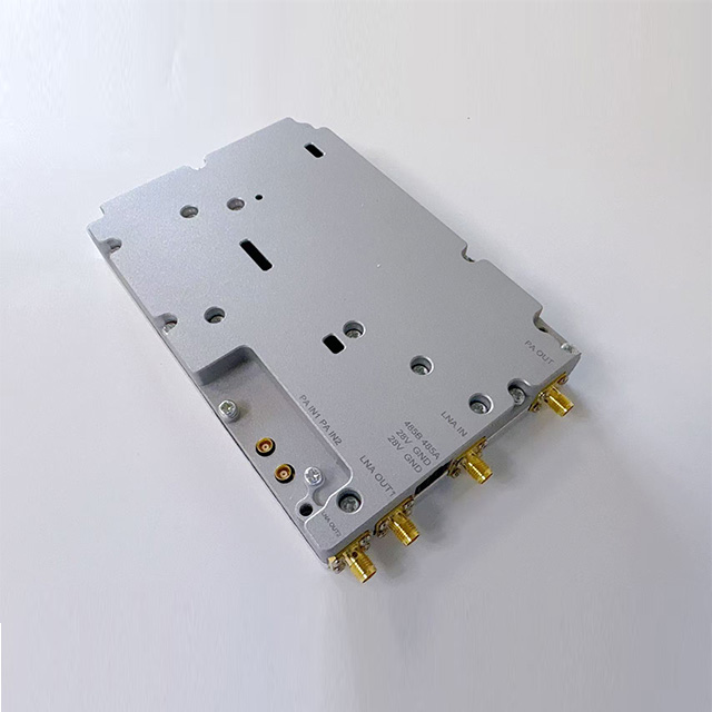
Procuring a high-specification RF component is only the first step. The system will drastically underperform if hardware integration is mishandled. The physical connections, circuit board layout, and cooling architecture dictate the final field performance.
The interface between the amplifier output and the antenna requires precise 50-ohm impedance matching. Industrial environments experience dynamic physical shifts. Metal machinery moves, doors open and close, and extreme weather alters external antennas. These conditions dynamically alter the antenna's physical properties, causing it to detune.
When the impedance mismatches, the antenna cannot radiate all the supplied energy. The unradiated energy reflects backward into the RF circuit. We measure this reflection as the Voltage Standing Wave Ratio (VSWR). High VSWR causes voltage peaks that exceed the breakdown voltage of the RF transistors. This reflected power degrades overall efficiency, generates dangerous excess heat, and risks catastrophic, permanent hardware damage.
Circuit board design heavily influences high-frequency RF performance. Trace routing, grounding strategies, and parasitic capacitance alter the intended frequency response. If a PCB layout lacks proper grounding vias, it creates unintended feedback loops, leading to wild signal oscillations.
RF engineers and hardware layout teams must collaborate closely. They must control trace impedances meticulously and isolate high-power RF lines from sensitive digital control signals. Even a millimeter of incorrect trace routing can introduce parasitic inductance, severely narrowing the amplifier's usable bandwidth.
Heat dissipation is a core determinant of system reliability. It cannot remain an afterthought in the design process. Hardware teams must engineer aggressive thermal pathways to pull heat away from the semiconductor die. Effective thermal management involves several strict architectural requirements:
Conductive Heat Sinks: Heavy aluminum or copper extrusion blocks must mate perfectly with the RF component, using high-quality thermal interface materials to prevent microscopic air gaps.
Thermal Vias: The PCB must feature dense arrays of copper-plated holes directly beneath the RF chip. These vias transfer heat instantly from the top layer to the bottom chassis.
Active Cooling Contingencies: For continuous, maximum-power loads, engineers must integrate ruggedized fans or liquid cold plates to maintain safe junction temperatures under 24/7 operation.
Industrial networks rarely remain static. As facilities upgrade to Industry 4.0 standards, network architects must scale RF infrastructure to support denser device populations and heavier data loads.
Expanding an industrial network shifts the baseline requirements for RF power. Adding fleets of automated robotics or thousands of low-latency safety sensors exponentially increases data density. A single-channel, low-power system that previously handled basic telemetry will fail under the load of high-definition video streams required by modern AGVs. Architects must evaluate not just current throughput needs, but the projected capacity demands five years down the line.
To meet these scaling demands, engineers often deploy advanced multi-channel setups. Implementing a Dual Channel RF Power Amplifier solves several distinct architectural challenges.
First, dual-channel setups enable MIMO (Multiple Input Multiple Output) technology. MIMO uses spatial multiplexing to bounce multiple data streams off metallic factory walls, actively using multipath reflections to increase data throughput and eliminate signal fading. Second, they drive complex phase array systems for directional beamforming. Finally, they provide critical hot-standby failover redundancy. If channel A suffers a hardware fault, channel B immediately assumes the load, ensuring zero downtime for mission-critical SCADA links.
Multi-channel configurations introduce severe implementation risks regarding physical space. Compact industrial enclosures limit the available footprint. Adding multiple high-power channels dramatically increases the cumulative power draw and doubles the thermal output. System architects must carefully budget heat dissipation. Cramming high-power multi-channel modules into small, sealed NEMA-rated boxes without appropriate thermal calculations guarantees rapid overheating and system failure.
Selecting the right hardware requires a disciplined evaluation framework. You must look far beyond standard promotional materials and rigorously vet components for actual industrial survivability.
You must evaluate an Industrial RF Power Amplifier through strict regulatory and durability lenses. Consumer certifications do not suffice here. A proper evaluation requires verifying specific industrial standards:
Regulatory Compliance: Verify FCC (North America) or ETSI (Europe) certifications to ensure the device maintains strict spectral masks and does not cause illegal interference in adjacent bands.
Environmental Ruggedness: Look for IP ratings (e.g., IP67) that guarantee absolute protection against metallic dust ingress and high-pressure water jets used in factory washdowns.
Mechanical Resilience: Demand MIL-STD-810G (or similar) compliance, verifying the component can survive continuous heavy vibration from industrial stamping presses and high-impact physical shocks.
Never commit to a volume purchase based purely on a printed datasheet. You must independently verify the vendor's claims. Advise your procurement and engineering teams to request detailed, long-term reliability test data. Ask the vendor for historical Mean Time Between Failures (MTBF) calculations derived from actual field deployments, not theoretical laboratory estimates.
Furthermore, demand comprehensive thermal stress reports. These reports should show how the amplifier performs after thousands of hours of continuous thermal cycling. Most importantly, request an Evaluation Board (EVB). An EVB allows your engineering team to plug the amplifier directly into your specific system architecture. You can then test its linearity, current draw, and heat generation under your exact environmental conditions before finalizing your network design.
Selecting the correct RF infrastructure demands a rigorous, evidence-based approach. We must look beyond theoretical peak output power metrics. True industrial reliability requires evaluating sustained thermal stability, strict signal linearity, and complex hardware integration parameters.
Understanding how components react to harsh environmental stress, severe impedance mismatches, and heavy duty cycles allows you to architect networks that simply do not fail. Objective evaluations of multi-channel capabilities and rigorous verification of vendor testing data directly mitigate the risk of catastrophic network downtime.
We encourage you to take proactive steps today. Request an evaluation board from your hardware vendor. Consult directly with an RF application engineer to discuss your specific impedance matching challenges, and deeply review the sustained CW technical spec sheets for your upcoming industrial deployment.
A: Industrial environments experience dynamic physical shifts, moving metal machinery, and harsh weather conditions that actively exacerbate antenna detuning. Poor impedance matching creates high Voltage Standing Wave Ratios (VSWR). This forces unradiated RF power to reflect backward into the amplifier. In high-power industrial components, this reflected power generates immense heat and can rapidly destroy the RF transistors permanently.
A: Frequency Division Duplexing (FDD) requires continuous, simultaneous transmission and reception on different frequencies. This demands stringent signal isolation and exceptional linearity to prevent spectral leakage from blinding the receiver. Time Division Duplexing (TDD) switches between transmitting and receiving. FDD components endure significantly higher continuous thermal loads than TDD devices.
A: Operating near saturation maximizes power efficiency but severely compromises linearity. The amplifier begins clipping the signal peaks, causing severe signal distortion. This distortion violates regulatory spectral masks and heavily corrupts data symbols in complex digital modulation schemes like QAM, ultimately leading to dropped packets and failed industrial network links.
A: Architects specify dual-channel setups when the environment demands spatial multiplexing (MIMO) to overcome severe multipath fading common in dense, metal-heavy factories. They are also mandatory when driving directional phase array antennas, or when mission-critical SCADA networks require immediate hot-standby hardware redundancy to prevent catastrophic operational downtime.


