
丨
Views: 0 Author: Site Editor Publish Time: 2026-10-12 Origin: Site


The architectural shift from 4G LTE to 5G Massive MIMO has fundamentally altered spectrum allocation across the telecom industry. This ongoing evolution forces hardware engineering teams to critically evaluate their front-end radio designs. A core conflict quickly emerges during this evaluation process. The choice between Time Division Duplexing (TDD) and Frequency Division Duplexing (FDD) directly dictates your system's thermal budget. It also determines stringent linearity requirements and the overall efficiency of your hardware modules. You must balance these physical constraints carefully to ensure network reliability.
In this article, we define the practical operational realities of both architectures. We explore the specific implementation risks associated with continuous transmission versus burst-mode cycles. We also outline clear shortlisting criteria to streamline your procurement and design process. By the end of this guide, RF engineers and technical buyers will possess the knowledge needed to select the optimal component for their specific network deployment. You will learn exactly how to match your front-end hardware to your environmental and regulatory constraints.
Operational modes dictate PA design: FDD requires continuous operation and heavy thermal management; TDD operates in bursts, requiring high-speed switching and transient stability.
Hardware footprint varies: FDD systems rely on physical duplexers to isolate continuous signals, whereas a TDD RF Power Amplifier uses high-speed switches, reducing BOM complexity.
Integration is the future: Modern 5G deployments increasingly rely on the Integrated RF Power Amplifier to solve space constraints in dense TDD Massive MIMO arrays.
Selection hinges on deployment environment: FDD dominates legacy macro-cells requiring wide-area coverage, while TDD dominates high-capacity, spectrum-efficient 5G deployments.
RF front ends face a consistent baseline problem regardless of the network generation. They must amplify incoming signals to high power levels without distorting the underlying complex modulation scheme. However, the chosen duplexing method fundamentally changes the physical stress placed on the underlying silicon. You cannot treat all transmission protocols equally during the hardware design phase. Understanding this core operational divide is critical for ensuring component longevity and signal integrity.
FDD introduces a highly demanding operational reality. It relies on simultaneous transmission and reception across separate, dedicated frequency bands. This protocol means the transmitter remains constantly active. It never powers down during an active data session. The component handles a continuous, unrelenting current draw. This persistent "on" state creates unique challenges for hardware stability. Engineers must design the underlying semiconductor materials, such as LDMOS or Gallium Nitride (GaN), for maximum sustained output without structural degradation.
TDD operates under a completely different physical paradigm. Transmission and reception occur on the exact same frequency band. They simply alternate in time, often separated by just a few milliseconds. The module operates in a highly dynamic duty-cycled "burst" mode. It cycles on and off rapidly to share the channel. This methodology requires incredibly precise timing synchronization from the baseband processor. The silicon experiences alternating periods of high electrical stress and absolute zero load. We must account for this rapid switching dynamic during the early stages of circuit design.
Constant transmission generates immense amounts of heat within the radio unit. This continuous thermal load fundamentally shapes FDD hardware architecture. A FDD RF Power Amplifier cannot rely on idle periods to cool its internal junctions. Heatsink design therefore becomes a primary constraint for the mechanical engineering team. Thermal dissipation capabilities strictly dictate the physical size and weight of the final radio enclosure. You must engineer robust passive or active cooling solutions to prevent thermal runaway and permanent junction degradation.
Next, you must carefully consider the duplexer penalty. FDD systems require bulky cavity or acoustic filters. The industry refers to these isolation filters as duplexers. They physically prevent the high-power transmit signal from leaking into and blinding the highly sensitive receive path. However, physical filters introduce significant insertion loss. Even a 1.5 dB loss through a filter forces the system to output substantially more raw power to compensate. Increased raw output further compounds the baseline thermal load. It creates a challenging feedback loop for hardware designers.
Linearity also suffers under constant, heavy operational stress. Modern modulation schemes, such as 256-QAM, demand strict Error Vector Magnitude (EVM) compliance. Maintaining ultra-low out-of-band emissions during continuous high-power operation is mechanically difficult. This requirement strictly limits the maximum theoretical efficiency you can achieve. Engineers often operate these continuous systems backed off heavily from their peak saturation power. This deliberate back-off preserves signal linearity but drastically sacrifices electrical efficiency. Balancing these competing demands requires deep, specialized RF expertise.
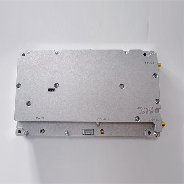
Burst transmission introduces incredibly strict transient response constraints. A TDD RF Power Amplifier must power up, stabilize its bias networks, and power down within extremely tight microsecond tolerances. Sluggish electrical transitions cause severe network-wide problems. Slow power-down cycles overlap with the incoming receive sequence. This overlap creates devastating self-interference within the radio. Conversely, slow power-up phases degrade the beginning of the transmitted data burst, causing packet loss. Precision timing at the microsecond level is non-negotiable.
Duty cycles, however, drastically improve overall baseline efficiency. These specialized systems remain active for only a fraction of the total operational time. A typical dense deployment might utilize a 50% or 75% transmit duty cycle. This built-in resting period significantly lowers overall average thermal dissipation. You can achieve much denser array configurations because the average heat load drops substantially. Engineers capitalize on this thermal advantage to build tighter, highly compact Massive MIMO antenna arrays.
TDD also fundamentally changes the filtering approach. It completely eliminates the need for massive physical frequency duplexers. Instead, the architecture utilizes high-speed Tx/Rx semiconductor switches to route signals. Solid-state switching drastically reduces post-PA insertion loss. The amplified signal travels a much cleaner, more direct path to the radiating antenna element. This switch-based routing dramatically shrinks the overall hardware footprint. It allows you to fit incredibly complex multi-channel arrays into much smaller, lighter physical enclosures.
Selecting the right front-end architecture requires a methodical evaluation process. You must weigh raw spectrum availability against your strict hardware footprint limitations. The physical deployment environment ultimately dictates the winning technology.
First, rigorously evaluate spectrum availability and regulatory compliance. FDD works best for legacy paired spectrum allocations. You typically find these symmetrical pairs in sub-3 GHz frequency bands. The network intrinsically requires symmetrical traffic allocations for maximum spectrum efficiency. Conversely, TDD acts as the undisputed standard for high-frequency 5G networks. This includes highly utilized C-band and mmWave deployments. Finding paired spectrum at these elevated frequencies is virtually impossible globally. Furthermore, TDD handles asymmetrical data traffic brilliantly. It dynamically allocates more time slots to heavy downlink traffic while keeping uplink slots minimal.
Second, thoroughly analyze the hardware footprint and BOM complexity. FDD demands a significantly higher discrete BOM count. Large physical duplexers take up massive amounts of board space. The associated heavy thermal management systems add unacceptable bulk and tower weight. TDD requires much smaller, surface-mounted components. Lower physical filter counts enable highly miniaturized PCB designs. You can shrink the entire remote radio head substantially.
Finally, consider the critical role of massive integration. 5G Massive MIMO demands extreme board-level miniaturization. You cannot physically fit 64 discrete transmitter paths into a standard, wind-load-compliant enclosure. When utilizing an Integrated RF Power Amplifier, TDD is inherently easier to integrate at commercial scale. Manufacturers skillfully combine the main PA, the low-noise amplifier (LNA), and the high-power switch into a single compact module. This deep integration drives the feasibility of dense 32T32R or 64T64R antenna arrays.
Evaluation Dimension | FDD Architecture | TDD Architecture |
|---|---|---|
Spectrum Type | Paired (Symmetrical) | Unpaired (Asymmetrical) |
Primary Frequency Bands | Sub-3 GHz (Legacy LTE/5G) | C-band & mmWave (5G NR) |
Duplexing Component | Physical Duplexer (Cavity/Acoustic) | High-Speed Tx/Rx Solid-State Switch |
Thermal Profile | Continuous Heavy Heat Load | Duty-Cycled (Lower Average Heat) |
MIMO Scalability | Low (Bulky footprint limits channels) | High (Ideal for 32T/64T Dense Arrays) |
Every complex RF design requires specific compromises. Recognizing implementation risks early prevents costly hardware redesigns later. You must systematically mitigate these specific engineering trade-offs during the initial development cycle.
Peak-to-Average Power Ratio (PAPR) challenges both topologies heavily. Complex OFDM signals exhibit extremely high PAPR spikes. Power Amplifiers must maintain strict linearity during these massive, sudden signal spikes. However, TDD systems face an additional layer of severe complexity. They must handle high PAPR while simultaneously managing mechanical thermal cycling stress. The rapid on/off states cause micro-fluctuations in die temperature multiple times per second.
This rapid switching also introduces severe memory effects. Thermal and electrical memory effects rapidly degrade overall signal quality. If the internal die temperature varies too wildly between bursts, the semiconductor behaves unpredictably. This degradation primarily impacts the Adjacent Channel Leakage Ratio (ACLR). You must meticulously compensate for these transient memory effects using advanced Digital Pre-Distortion (DPD). Properly tuned DPD algorithms predict and proactively cancel out these transient nonlinearities before they reach the antenna.
Continuous transmission in paired spectrum creates severe co-site interference risks. FDD systems output very high power constantly without pausing. This constant barrage of RF energy can easily desensitize nearby sensitive receivers on the same cellular tower. You must conduct rigorous isolation testing during prototyping. Ground plane shielding, cavity isolation, and strict layout separation are absolutely paramount for success.
Ignoring transient thermal spikes when calculating overall cooling limits for rapid burst-mode operations.
Underestimating the severe post-PA insertion loss introduced by legacy acoustic or cavity duplexers.
Failing to tune DPD algorithms for the exact duty cycle percentages used in your live network deployment.
Overlooking strict ground plane isolation when routing continuous high-power signals near highly sensitive receive paths.
Making the final component selection requires a clear, objective decision matrix. You must directly align your hardware choice with your specific network topology and available spectrum assets.
You should shortlist FDD for wide-area macro coverage networks. It remains the reliable backbone for rural LTE and early low-band 5G deployments. It perfectly supports specific industrial applications requiring absolute zero latency for mission-critical symmetrical data. Environments possessing expensive legacy paired spectrum licenses also demand this continuous architecture. The steady, continuous link guarantees uninterrupted baseline coverage across wide geographic regions.
You should immediately shortlist TDD for urban, ultra-dense networks. It heavily dominates Massive MIMO deployments and critical C-band 5G rollouts globally. Choose this agile path for scenarios demanding heavy asymmetrical data optimization, like video streaming. It is often the only viable option when your physical enclosure size strictly dictates highly compact, integrated hardware.
Your actionable next step is straightforward. Request specialized evaluation boards (EVBs) from your chosen component vendors. Use these boards in your lab to test continuous thermal performance for paired spectrum modules. Alternatively, test switching transient stability under your specific carrier aggregation scenarios using vector signal analyzers. Empirical lab data will confidently validate your theoretical design assumptions before mass production.
The choice between these two distinct architectures is rarely about which is objectively better in a vacuum. The decision depends entirely on your licensed spectrum assets, your available thermal budget, and your physical hardware footprint limitations. Burst-mode structures excel in dense, high-capacity urban environments where space is at a premium. Conversely, continuous transmission frameworks provide unwavering, robust coverage over broad geographic areas.
As cellular networks move rapidly toward high-capacity 5G formats, the industry clearly favors burst-mode transmissions. Highly compact, integrated RF solutions are dominating new macro-cell and small-cell designs. The mechanical ability to stack 64 transmitters in a single unit makes this technology indispensable for modern capacity demands. However, legacy continuous architectures remain critical for establishing robust baseline coverage in rural sectors.
Take decisive action on your radio unit design today. Consult with an RF applications engineer to discuss your specific PCB layout challenges. Download comprehensive technical datasheets to compare specific efficiency curves. Evaluate the Digital Pre-Distortion requirements for your target modulation scheme early in the process. Secure your evaluation boards and begin transient or thermal testing immediately to ensure project success.
A: While broadband silicon can technically amplify the frequencies used by both, the surrounding front-end module is entirely different. Filters, switches, and DPD tuning mechanisms vary drastically between the two operational modes. Dual-mode capability usually requires specialized, discrete architectures rather than simple single-chip solutions. You cannot easily swap one mode for the other on the fly.
A: 5G Massive MIMO heavily favors TDD. Putting 64 FDD transceivers in a single radio unit is unfeasible. The physical size of 64 cavity duplexers is simply too large. Furthermore, the continuous thermal load would melt the enclosure. TDD eliminates bulky filters and lowers average heat, allowing for the necessary miniaturization in 5G arrays.
A: Thermal cycling stresses semiconductor junctions. Rapid heating and cooling during bursts causes mechanical fatigue at the microscopic level. High-quality components require robust die-attach materials and advanced packaging to survive this. Without proper thermal design, this rapid cycling can accelerate long-term degradation compared to the steady-state heat of continuous transmission.


